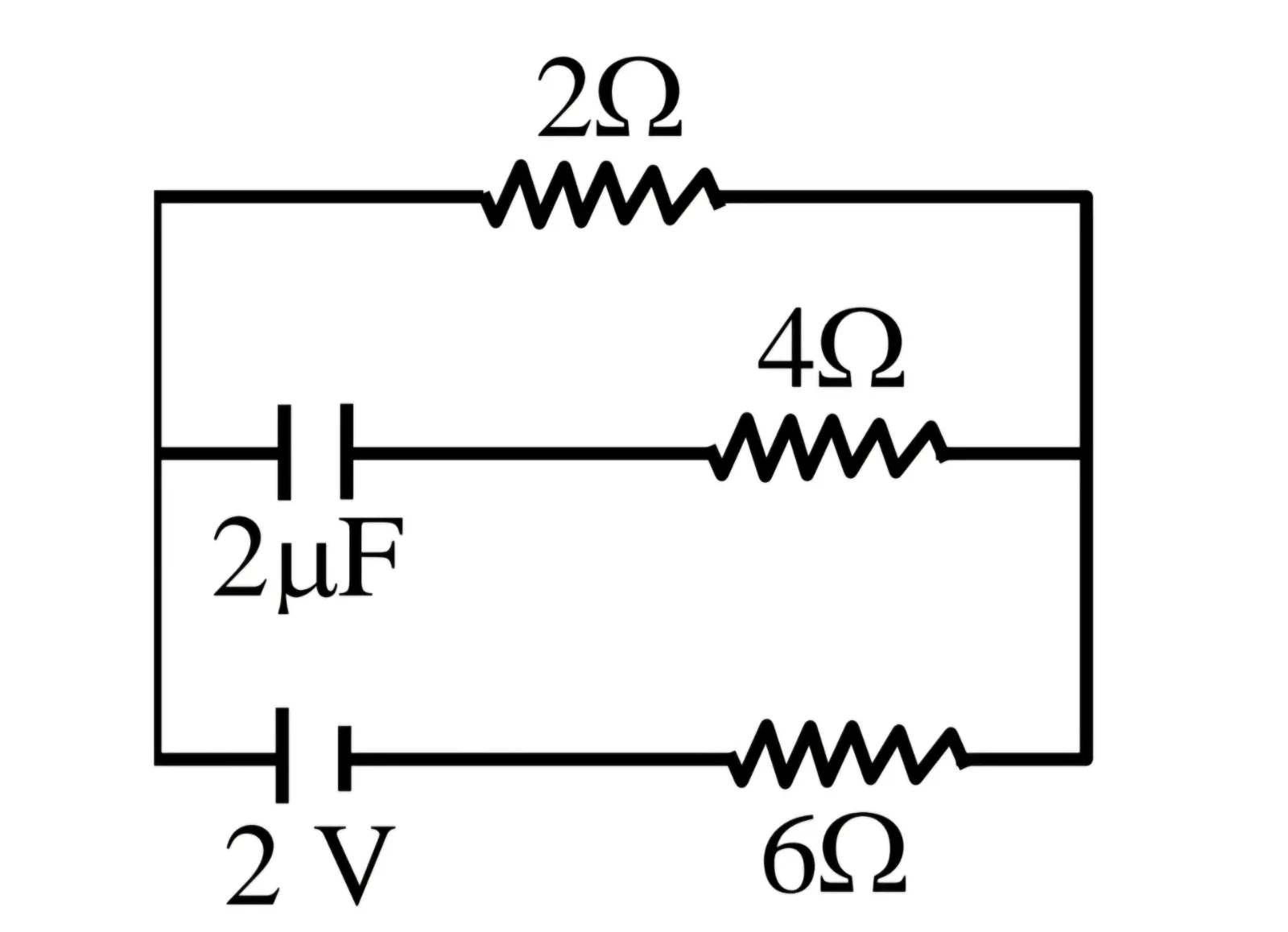
In the circuit shown in the figure, a 2 μF capacitor is in a branch with a 4 Ω resistor, while the other branches contain a 2 Ω resistor and a 2 V source in series with a 6 Ω resistor. After steady state is reached, what is the potential difference across the capacitor?
Physics · Capacitor · RC circuit
In the circuit shown in the figure, a 2 μF capacitor is in a branch with a 4 Ω resistor, while the other branches contain a 2 Ω resistor and a 2 V source in series with a 6 Ω resistor. After steady state is reached, what is the potential difference across the capacitor?
Options