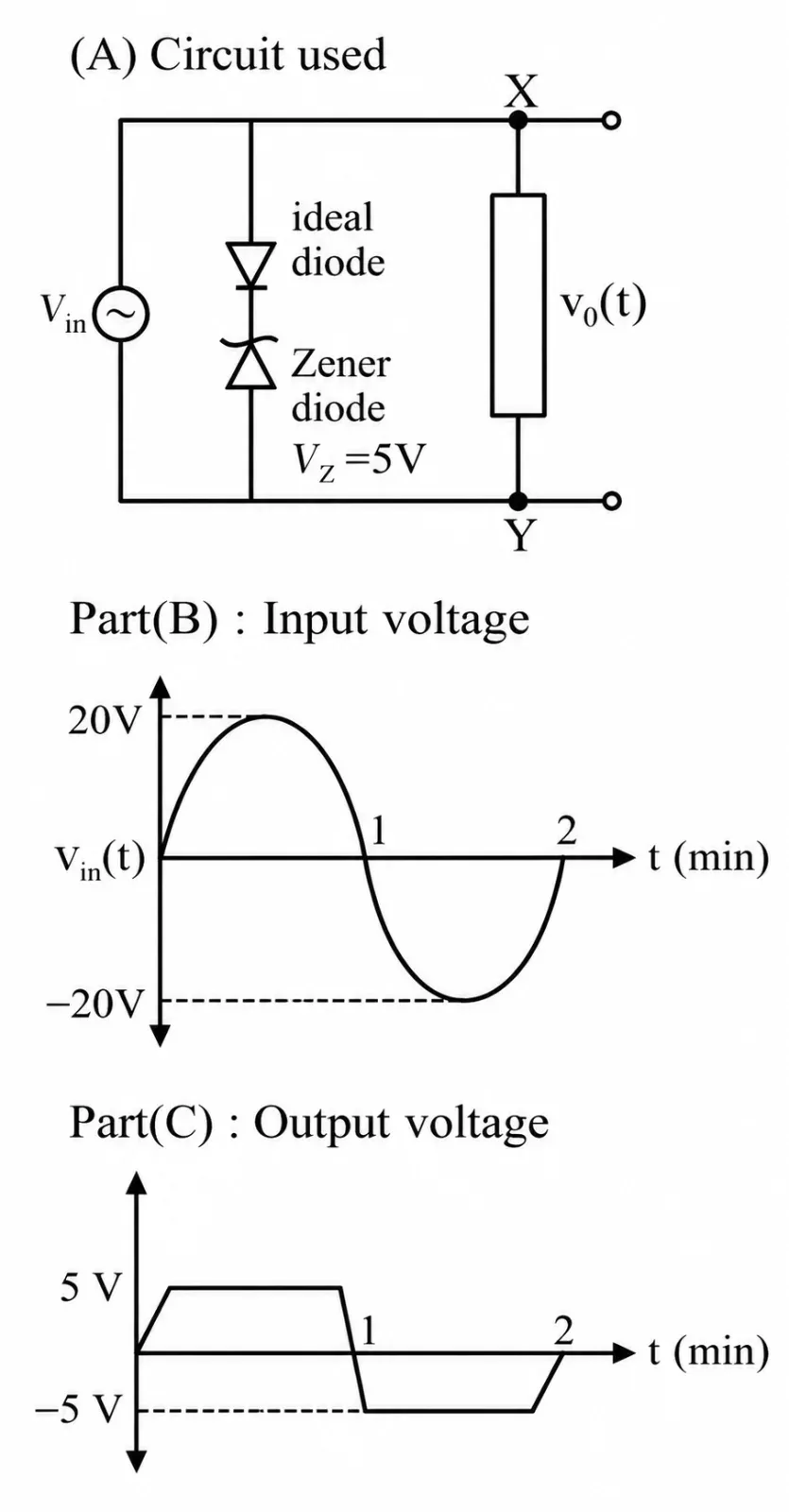
In the diode-Zener clipper circuit shown in the figure, the input is a sinusoidal voltage varying between +20 V and -20 V, while the observed output is clipped at approximately +5 V and -5 V. Which component arrangement must be connected between terminals X and Y?
Physics · semiconductor · application of diode and zener breakdown
In the diode-Zener clipper circuit shown in the figure, the input is a sinusoidal voltage varying between +20 V and -20 V, while the observed output is clipped at approximately +5 V and -5 V. Which component arrangement must be connected between terminals X and Y?
Options